 |
|
 12-01-2015, 03:28 PM
|
#61
|
|
Bronze Member
Join Date: Dec 2013
Posts: 39
|

Quote:
Originally Posted by gsm

I use a reasonably priced Uni-Trend Group Ltd. clamp-on Ammeter UNI-T Model UT203, I bought some years ago for around US $70.
|
I found a similar one for around $28. It will take a while to ship but the price is right.
Quote:
Originally Posted by gsm
In Post # 58 I tried to make AGM E-Trek owners aware that RT might have several substantially different alternator-configurations out there. Some variants would work better than others.
|
I will do some research to figure out what setup we have. I believe that the stock alternator connects to the battery separator and the front 12v bank and the aftermarket "3500w" alternator is connected to the 24v bank. I will have to confirm this with some deeper investigation.
I really appreciate all your advice and help on this subject. Our limitation is with the warranty that RT still has on the existing setup. We will keep waiting for them to produce a true fix. In the meantime I am happy to provide data for our current setup.
I am thinking of installing a data logging device to measure temperature and voltage of each cell/bank. I have been experimenting with Arduino's and the Raspberry pi for some other projects. Would that be a useful tool as we all keep working on a fix?
|

|

|
|
12-01-2015, 03:33 PM
|
#62
|
|
Bronze Member
Join Date: Dec 2013
Posts: 39
|
Quote:
Originally Posted by gsm
Up to now we all assumed that the second alternator of the AGM E-Trek is a high current 24-volt model. What if we are wrong? Could the second alternator be a 12-volt model with negative and positive terminals isolated from chassis ground? RT might have stacked the floating output of this second alternator on the 12-volts of the Sprinter alternator? So AGM E-Trek owners please check this out.
|
What would be the best way to find this out?
|
|
|
|
|
12-01-2015, 03:41 PM
|
#63
|
|
Platinum Member
Join Date: Jul 2012
Posts: 2,380
|
Arduino or Raspberry Pi would work fine I expect as standalone data loggers or networked if you want real time data to a computer. Good idea to instrument the system rather than trying to capture data using handheld meters.
|
|
|
|
|
12-01-2015, 04:35 PM
|
#64
|
|
Platinum Member
Join Date: Aug 2010
Location: Minnesota
Posts: 12,012
|
When I had our new system on the bench for testing, I was using a Beckman clamp on to a Fluke meter, and it worked fine, except you can't get on the battery jumpers well at all. I switched to checking for milivolt drop across various points, like crimps, battery connections, etc. It didn't really matter is the meter zeroed perfectly, and it didn't, as you are only doing comparison not absolute value. I was able to check all connections, crimps, and cable length issues very easily, and in areas that I could get at it with the clamp on, the results matched completely. I tried the same checking resistance, and could not get good results, but millivolt drop was good. Even if you do more sophisticated later, you can do this first to find mismatched cable lengths or bad connections as it is very easy.
|
|
|
|
|
12-01-2015, 04:56 PM
|
#65
|
|
Platinum Member
Join Date: Aug 2007
Location: Minnesota
Posts: 5,967
|
Quote:
Originally Posted by photolimo
I found a similar one for around $28. It will take a while to ship but the price is right.
I will do some research to figure out what setup we have. I believe that the stock alternator connects to the battery separator and the front 12v bank and the aftermarket "3500w" alternator is connected to the 24v bank. I will have to confirm this with some deeper investigation.
I really appreciate all your advice and help on this subject. Our limitation is with the warranty that RT still has on the existing setup. We will keep waiting for them to produce a true fix. In the meantime I am happy to provide data for our current setup.
I am thinking of installing a data logging device to measure temperature and voltage of each cell/bank. I have been experimenting with Arduino's and the Raspberry pi for some other projects. Would that be a useful tool as we all keep working on a fix? |
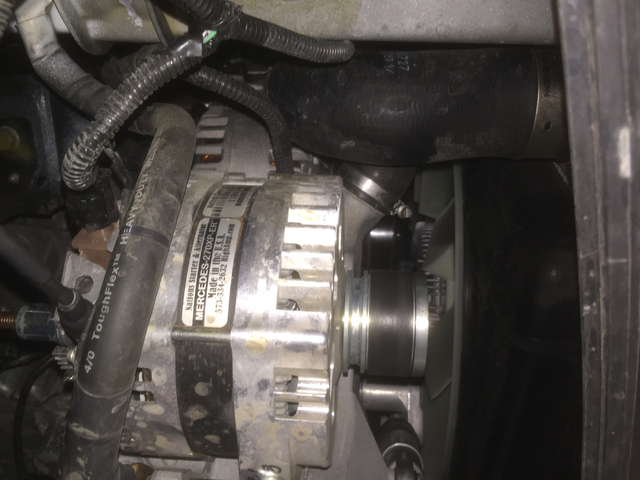
If you have a dual alternator I would be surprised if the engine alternator is connected to your house batteries in any way. Mine isn't. Also, can't you just look at your second alternator and see a name and model plate that will tell you what you have? I can do that as well. Right under the front bumper, here is mine in about the only location you can install one that I am aware of.
__________________
Davydd
2021 Advanced RV 144 custom Sprinter
2015 Advanced RV Extended body Sprinter
2011 Great West Van Legend Sprinter
2005 Pleasure-way Plateau TS Sprinter
|
|
|
|
|
12-02-2015, 03:13 AM
|
#66
|
|
Bronze Member
Join Date: Sep 2015
Location: Ottawa, Ontario, Canada
Posts: 32
|
photolimo
Post # 61 & 62
I agree with Daydd Post # 65, but markings are not always easy to see. Therefore, having another method may be helpful. Besides, you still want to find out how things are interconnected.
If the second alternator is a High current 24-volt type it will most likely carry the current from the negative connection via its body to the engine-block and then via an upgraded wire to chassis. It would be a mistake to rely on the Sprinter's engine to chassis ground, which is not going to be heavy enough, and voltage drops here could, depending how the Sprinter is wired, make headlights, etc. brighten as the high current flows. It might even upset the Sprinter's alternator-regulator depending how the latter samples the starter battery. Ideally the high current alternator, in addition to a positive post, needs a negative post, allowing connection of a sufficiently heavy gauge wire directly to where it is wanted.
If the second alternator is a 12-volt alternator stacked on the Sprinter's 12-volt alternator it definitely needs to have both a negative and a positive post. (The internal output windings and the three-phase rectifier bridge is isolated from the alternator body, i.e. floating.) With the negative connected to the positive of the Sprinter's battery. This connection could be direct to the battery or established every time an isolator closes. Measuring across the posts of the second alternator or wiring coming directly from it would show 12 volts. Measuring between the negative post and ground would give 12 volts. And of course between ground and the positive post you will find 24 volts.
In this scheme of things, the Sprinter's alternator would charge the lower 12-volt of the 24-volt battery-bank, and the second alternator the upper 12-volt part. Real balance between battery-halves is virtually impossible to achieve, therefore, a need to the have some sort of battery balance system between the 12-volt sections. Charging of the lower half depends on what the Sprinter's alternator can afford. The rating of the second alternator might have been trimmed back to account for this in part, as it only needs to charge pairs CG and DH.
You got a great price on the meter. It is the same one I bought. Popular with local tech-school students at the time. You will find it handy to have on board. It being properly insulated gives you personal protection when dealing with currents on 120 volt AC equipment.
gregmchugh
Post # 61 & 63
Data logging is a great idea. Logging the terminal voltage of eight batteries can be expensive, particularly if you add the cost of eight current sensors. My own inclination is to start with a simple approach. Learn. Let the findings will indicate what to do next.
booster
Post # 64
I agree that milli-volt readings can be successfully used in situations where equal length and gauge of cable is used to take a sample for comparison measurements. It is the same concept as using a shunt. Your results show that this is a very useful technique. At low milli-volt levels it is important that the probes sample at the same type of metal.
Certainly jumpers allow this this kind of voltage-drop measurement. For a long cable-run to the engine compartment it becomes impossible for the meter leads to reach both terminals. In this case, one can take a measurement between sowing-pins driven a certain distance apart, through the insulation into the copper. One can even make a convenient jig with spaced pins and leads to the meter.
Regards All
GerryM
|
|
|
|
|
12-02-2015, 06:03 PM
|
#67
|
|
Platinum Member
Join Date: Jul 2012
Posts: 2,380
|
Data logging for 8 voltage and temperature channels would cost about $60 with the Arduino Mega ($45, 16 analog input channels) and 8 analog temp sensors. Is that expensive?
Lower cost options might be available but this Arduino board has the 16 analog input channels onboard. That is the price for a "real" Arduino board, there are probably clones that are cheaper. This stuff is versatile and reusable for other projects.
|
|
|
|
|
12-02-2015, 10:00 PM
|
#68
|
|
Bronze Member
Join Date: Dec 2013
Posts: 39
|
Quote:
Originally Posted by gregmchugh
Data logging for 8 voltage and temperature channels would cost about $60 with the Arduino Mega ($45, 16 analog input channels) and 8 analog temp sensors. Is that expensive?
Lower cost options might be available but this Arduino board has the 16 analog input channels onboard. That is the price for a "real" Arduino board, there are probably clones that are cheaper. This stuff is versatile and reusable for other projects.
|
This is exactly how I was going to go about it.
$10 Arduino Mega
$3 Prototype Shield
$5 Data Storage & Clock Shield
A whole bunch of resistors for gathering the correct voltage readings and maybe a temperature module for front/back difference readings.
I may use the existing 500A and 100A current shunts to take amperage readings but that would be icing on the cake. Keep it simple to start.
|
|
|
|
|
12-02-2015, 10:26 PM
|
#69
|
|
Bronze Member
Join Date: Sep 2015
Location: Ottawa, Ontario, Canada
Posts: 32
|
gregmchugh
Post # 67
photolimo
Post # 68
I am not interested in a dispute over what is costly or not. I never played with this technology. It would be wonderful if all the instrumentation can be done for under $100.
I see some complications that you may be overlooking. You will need to measure floating voltages and currents. Temperature probes are normally already electrically isolated. This means that the output voltage can be easily tied into an A/D converter.
If you want to determine voltage across each of the eight batteries you need to make the voltage measurement directly between each battery's lead-posts. This requires a floating differential measurement, with the electrically isolated A/D converted result transferred to the digital buss. Each floating A/D converter will also need its own floating power source.
You cannot just take the voltage between chassis/ground and all positive battery terminals and calculated differences since you have not eliminated cable-drops. Taking analog signals any distance would likely entail noise pickup.
In the case of the eight battery-currents, you need a magnetic sensor for each battery. Again the A/D converted result is transferred to digital buss. Fortunately, like with the temperature sensors the necessary electrical isolation is provided by the magnetic field, however individual power sources might be needed. If analog the sensor may provide its own output potential. If you were to use eight shunts to measure current you have the same problems as the battery voltage measurements, and you will be dealing with much smaller potentials.
By the way, if you use eight temperature, voltage and current sensors you will need to assure that they track acceptably closely to each other.
Best Regards
GerryM
|
|
|
|
|
12-02-2015, 11:19 PM
|
#70
|
|
Bronze Member
Join Date: Dec 2013
Posts: 39
|
Quote:
Originally Posted by gsm
You cannot just take the voltage between chassis/ground and all positive battery terminals and calculated differences since you have not eliminated cable-drops. Taking analog signals any distance would likely entail noise pickup.
|
I was thinking of taking voltage measurements at each battery (with a common ground) then using the program to divide the difference to get a per cell measurement. Some discussion on the topic here.
I am not planning on using current measurement, and there would be one temp sensor in the front and one in the back to get the general difference.
I do not claim to have this figured out, I am new to most of this. I appreciate any constructive feedback.
|
|
|
|
|
12-03-2015, 01:04 AM
|
#71
|
|
Platinum Member
Join Date: Jul 2012
Posts: 2,380
|
Quote:
Originally Posted by gsm
gregmchugh
Post # 67
I am not interested in a dispute over what is costly or not. I never played with this technology. It would be wonderful if all the instrumentation can be done for under $100.
Best Regards
GerryM
|
OK, GerryM, you said it would be expensive without providing any calibration of what level of cost was expensive in your mind. I provided an estimate of the potential cost of an Arduino solution. I simply asked if that was expensive in your view. You brought up the issue of cost and I responded. So, how exactly am I starting a dispute?
With your attitude, I think you will fit in very well here. Highly knowledgeable, opinionated, and quick to react in a negative manner in response to a seemingly benign question that seems to have offended your sensibilities in some way.
Welcome to the Class B armchair engineer club...
|
|
|
|
|
12-03-2015, 01:31 AM
|
#72
|
|
Bronze Member
Join Date: Sep 2015
Location: Ottawa, Ontario, Canada
Posts: 32
|
gregmchugh
Your Post #71
Well my point exactly
Regards
GerryM
|
|
|
|
|
12-03-2015, 02:28 AM
|
#73
|
|
Platinum Member
Join Date: Jul 2012
Posts: 2,380
|
Very good GerryM, I managed to last a few weeks this time before this type of BS happened. Life is too short for this, you all have fun with yourselves, I am sure I will get lots of useful info by just reading all your posts and likely some entertainment watching you boys at play...
|
|
|
|
|
12-03-2015, 11:38 AM
|
#74
|
|
Platinum Member
Join Date: Oct 2006
Location: New Brunswick, Canada
Posts: 8,828
|
Just trying to lighten the mood here 
Quote:
Greg: I'm fed up up with you all and am leaving and taking my Arduino with me!
Forum: Greg, eat a Snickers.
Greg: Why?
Forum: Because you get cranky when you're hungry.
Forum: Better?
Greg: Better.
|
|
|
|
|
|
12-04-2015, 02:46 AM
|
#75
|
|
Platinum Member
Join Date: Jul 2012
Posts: 2,380
|
Golly Gee, you guys didn't have to end the party. I hope it wasn't because I got annoyed by one of the guests and went home early. I am sure you will have plenty of fun without me...
|
|
|
|
|
12-04-2015, 02:30 PM
|
#76
|
|
Platinum Member
Join Date: Oct 2006
Location: New Brunswick, Canada
Posts: 8,828
|
Yes, lets get this topic going again.
I think I'd start with simple checks as suggested by a couple of posters. That would rule out any loose connections etc.
If it was mine and off warranty I'd probably skip ahead to GerryM's relatively easy rewire here: http://www.classbforum.com/forums/f5...html#post36232
I think you could get approval from RT though. It might work out way better for them than replacing a lot of AGM batteries over the term of the 6 year special E-Trek warranty. 
There were a few questions that still need to be answered before any rewiring including finding out if it has a 24v alternator.
With that rewire both the 12V and 24V system have access to the full ah capacity of the battery bank. 
|
|
|
|
|
12-04-2015, 03:02 PM
|
#77
|
|
Bronze Member
Join Date: Dec 2013
Posts: 39
|
Quote:
Originally Posted by markopolo
I think I'd start with simple checks as suggested by a couple of posters. That would rule out any loose connections etc.
|
I looked back and could not find what you were referring to. What would be the process for checking the connections with an ohm meter again?
Quote:
Originally Posted by markopolo
There were a few questions that still need to be answered before any rewiring including finding out if it has a 24v alternator.
|
I will get under the engine this weekend, and I have an Ammeter on order coming on Sunday.
|
|
|
|
|
12-04-2015, 03:09 PM
|
#78
|
|
Platinum Member
Join Date: Oct 2006
Location: New Brunswick, Canada
Posts: 8,828
|
Quote:
Originally Posted by photolimo
I looked back and could not find what you were referring to. What would be the process for checking the connections with an ohm meter again?...........
|
I got a bit lost with that part of the discussion so can't help. Someone else should be able to help (us).
|
|
|
|
|
12-04-2015, 03:12 PM
|
#79
|
|
Site Team
Join Date: Jul 2013
Posts: 5,340
|
Quote:
Originally Posted by markopolo
I think you could get approval from RT though.
|
Why would you need RTs "approval"? There is no way they are going to warrant your work anyway (why should they?). And, at least in the U.S., MagnusonMoss makes it illegal for them to deny warranty claims based on aftermarket modifications, unless, of course, the modifications actually CAUSE the failure.
__________________
Now: 2022 Fully-custom buildout (Ford Transit EcoBoost AWD)
Formerly: 2005 Airstream Interstate (Sprinter 2500 T1N)
2014 Great West Vans Legend SE (Sprinter 3500 NCV3 I4)
|
|
|
|
|
12-04-2015, 03:20 PM
|
#80
|
|
Platinum Member
Join Date: Oct 2006
Location: New Brunswick, Canada
Posts: 8,828
|
I'd try the approval route first. They might be very interested in seeing the results. And, they might point out something missed on the forum.
|
|
|
|
|
|
 Posting Rules
|
You may not post new threads
You may not post replies
You may not post attachments
You may not edit your posts
HTML code is Off
|
|
|
|
 » Recent Threads
 |
|
|
|
|
|
|
|
|
|
|
|
|
|
|
|
|
|
|
|
|
|
|
|
|
|
|
|
|
|
|
|
|
|


 Linear Mode

